This page is the sixth in a series of pages introducing the Multi-Gigabit Transceiver (MGT), and the second page about the PMA.
Introduction
In the previous page, the transmission of bits through the physical channel with the help of the PMA was discussed. However, this data stream is not always turned on: It's possible to turn off large parts of the MGT for the purpose of saving power. This is important in particular when the MGT implements SATA, PCIe, or SuperSpeed USB inside a laptop computer. When these protocols are applied, it's a waste of energy to keep the physical link active when there is no data to transmit.
An MGT must therefore have the ability to transfer into a low-power state. Even more important, an MGT must have the ability to notify the other side when it's time to wake up from this low-power state. The PMA is responsible for generating and detecting OOB signals for this purpose (and other purposes as well).
Out-of-band (OOB) signals consist of simple patterns of electrical activity on the same differential wires that are used for transmitting the data stream. These OOB signals can be transmitted only when the regular data stream is turned off. The most important thing about these signals is that they can be detected by the receiver with the help of very simple logic. This allows the MGT that receives an OOB signal to detect it even when this MGT is in a low-power state.
Another feature that MGTs support is the transmitter's ability to detect whether it is physically connected to another MGT (without making the other MGT do anything). This feature is called Receiver Detection.
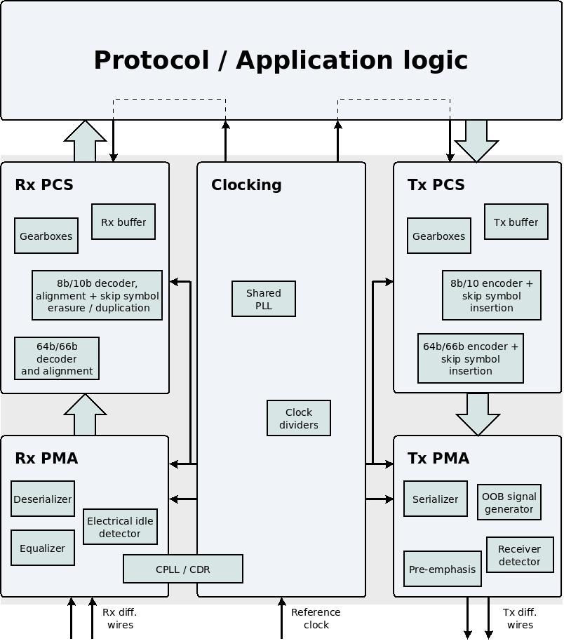
This page introduces these two capabilities: OOB signals and receiver detection. The block diagram from the two previous pages is shown here again for convenience:
Transmitting OOB signals
The Out-Of-Band (OOB) signal is usually a simple square-wave signal with a constant frequency. This signal can be transmitted only instead of the regular data stream, and never simultaneously with it.
Each protocol has different requirements on the shape of the OOB signal. An FPGA MGT usually has input ports allowing the application logic to request OOB signals in accordance with the most commonly used protocols (PCIe and SATA in particular).
The nomenclature and requirements from the OOB signals differ from one protocol to another. For example:
- The PCIe protocol calls its OOB signal a "Beacon". The requirements can be satisfied with a square wave signal having a frequency between 30 kHz and 500 MHz. However the protocol doesn't even require that the signal is periodic. The Beacon is used to wake up from a low-power state.
- The SATA protocol defines three type of OOB signals: COMRESET, COMINIT, and COMWAKE. The protocol defines these signal's formation accurately. COMRESET is used by the host side in order to reset the device. COMINIT is only sent by the device, and is used to initialize the link. COMRESET and COMINIT are exactly the same signal, but their meaning depends on which side sends them. COMWAKE is used by either side to wake up the link from a low-power state.
- The USB SuperSpeed protocol calls its OOB signal "Low Frequency Periodic Signaling" (LFPS). This is a square wave with a frequency between 10 MHz and 50 MHz. This signal is used for terminating a low-power state, but also for a variety of other purposes. In particular, the initial setup of the data stream consists of a strictly defined exchange of LPFS signals. The protocol defines several patterns of LFPS signals, each pattern having a different meaning. For example, if the host transmits an LFPS signal continuously during 100 ms, this is a requirement to reset the device.
Sometimes the MGT doesn't have the capability to generate an OOB signal that is adequate for a specific protocol. This can be solved by turning on the transmitter for sending data, and feeding the MGT with a data stream that corresponds to the desired signal pattern. In particular, if the MGT's encoding capabilities are turned off, the MGT behaves like as simple SERDES. The desired signal pattern can then be shaped arbitrarily with the help of the data for transmission. For example, a square wave can be generated by transmitting contiguous sequences of '0' and '1'. The main drawback of this solution is that the MGT's encoding capabilities are not used, so the encoding feature must be implemented in the application logic instead.
Electrical idle
When an MGT's transmitter is turned off or in a low-power mode, its output is usually in the electrical idle state. This means that the transmitter connects both differential output wires (D+ and D-) to ground. The voltage between these wires is hence zero, but each wire also has a zero voltage in relation to ground.
When the MGT is sleeping, the electrical idle state is the opposite to transmitting an OOB signal. Or, to summarize the three possible states of a transmitter:
- Transmission of data. The MGT is considered to be powered on only when in this state.
- Transmission of OOB
- Electrical idle
As already mentioned above, OOB is used only occasionally in order to wake up the other side from a low-power state, or as part of starting up the link. So most of the time, an MGT is either transmitting data or sleeping in the electrical idle state.
Detecting OOB signals
When an MGT is turned off or in a low-power state, its receiver may be required to detect if an OOB is transmitted by the other side. This is necessary for responding to a request to resume normal operation, in particular.
Most protocols don't specify the OOB signal's waveform accurately, but rather defines a range of possibilities. It's therefore not possible for the receiver to compare the arriving signal with an expected waveform. Instead, the OOB signal is detected when there is any activity on the differential wires. In other words, if the data stream is turned off, but the voltage on the differential wires changes too much for considering it an electrical idle, the explanation is that an OOB signal is transmitted by the other side.
For this reason, an FPGA MGT doesn't have an output port for the detection of an OOB. Rather, there is an output port that becomes high when the receiver detects electrical idle. The name of this port is usually something like "rx_elecidle".
Unfortunately, the MGT's detection mechanism for electrical idle can be unreliable. In particular, when the other side transmits a data stream, the behavior of the receiver's electrical idle detector is different from one MGT to another: It's possible that the MGT will detect electrical idle in this situation. It's likewise possible that the MGT will firmly detect that no electrical idle is present. It's also possible that random detections will occur. Each FPGA behaves differently.
Theoretically, this is not a problem, because why would there be a need to check for electrical idle when the data stream is active? But in real life, an MGT might transmit data even when the other side doesn't expect it. The application logic should therefore be designed to react correctly when it expects the other side to be turned off, but a regular data stream arrives instead.
Another problem with the detection of electrical idle is sensitivity to noise: The perfect electrical idle is when both differential wires have a zero voltage. As a result of noise, the receiver might measure a voltage that is enough to rule out electrical idle. The application logic is then at risk to interpret this as an OOB signal.
In conclusion, there is no simple solution for detecting OOB signals reliably. The application logic must be designed to cover up for the imperfections of the electrical idle detector.
Receiver detection
The PCIe protocol and SuperSpeed USB require the capability to detect if there is something connected to the other side of the link. This detection needs to be done without attempting to initiate communication with the other side. This feature is referred to as receiver detection.
This is required for SuperSpeed USB, because the computer needs to know when the device is physically disconnected from it. If such disconnection happens when the link is in a low-power state, the computer has no way to tell that something has happened: No activity is expected on the wires anyhow. Therefore, the protocol requires that the host performs a receiver detection every 100 ms. This allows the computer to verify that the device is still connected without wasting energy.
The PCIe protocol requires that receiver detection takes place on each PCIe slot before attempting to bring up the link with the device that is possibly connected to this slot. As bringing up the link involves powering up the MGT for transmission of data (a training sequence, more precisely), avoiding unnecessary attempts is important for saving energy.
The MGT's transmitter performs receiver detection by creating a short voltage pulse on its both output wires (D+ and D-). This is a common mode voltage pulse, so the same voltage with reference to ground is applied to both wires. If there is a receiver on the other side, a measurable current will flow through the receiver's termination resistors. This current affects the voltage at the transmitter's output. If there is no receiver on the other side, the current will be negligible. Hence the transmitter measures the voltage at its output shortly after the pulse's beginning, and determines accordingly whether a receiver exists on the other side or not.
The reason a pulse is needed (rather than a plain DC voltage) is that there is a capacitor between the transmitter and the receiver. Immediately after the pulse, an electrical current flows as the pulse voltage falls on the termination resistors of the transmitter and the receiver. As the capacitor charges, the current becomes lower, as with any RC circuit. If the voltage remains steady, the current becomes zero eventually.
It important to note, that receiver detection works only if the receiver's termination resistors are connected to ground for both D+ and D-. For example, the PCIe protocol requires that these termination resistors are 50Ω. It is possible to achieve the same differential impedance by connecting a 100Ω resistor between D+ and D-, without a connection to ground. If the termination is made this way, all functionalities will work properly except for receiver detection. The difference is that all other functionalities rely on the differential voltage between D+ and D-, but receiver detection is implemented by applying the same voltage on both wires. If the termination resistors aren't connected to ground in the middle, no current will flow, and hence the receiver will not be detected.
This wraps up the sixth page in this series about MGTs. The next page finishes this series with a few explanations about the MGT's clocking.